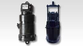
Electro Hydraulic Thruster
Electro Hydraulic Thruster

Introduction
In addition to wide range of applications in mechanical engineering applications, the thruster operated drum brakes are mainly used in material lifting and handling equipment, mainly because their 'Fial-to-safety' designs ensure safety to men and machines in the event of over failure. With the advancement in electricl drives and electronics, the drives have pushed the mechanical systems to high level of operations and demanding safer and reliable braking loads moving at much higher speeds than earlier. Continuous developments in product improvisation and assured quality checks, the thrusters offer compact, reliable yet economical solutions to most of the industrial applications..
Assembly and Function
The two main sub-assemblies of the hydraulic thruster, the electric motor and the hydraulic unit are co-axially assembled form the working unit. In the switched off state (de-energised) the piston is at its lowest position due to external load (as brake spring of the drum brake), and the brake is applied. When energized, the electric motor drives the pump and delivers working fluid under the piston axially in the guided path, and delivers thrust or force required to operate the attached devise (like thruster brake) via the piston rod and the eye-lug attached to it. The working stroke can be steplessly controlled by external load. The thruster is designed for long trouble free service. The motor windings are designed to meet contingencies. The bearings are adequately sized.
Technical Specification
|
Model No. |
Force (Kg.m) |
Stroke (MM) |
|
RI-EHT-18 |
18 |
51 |
|
RI-EHT-34 |
34 |
51 |
|
RI-EHT-46 |
46 |
51 |
|
RI-EHT-68 |
68 |
76 |
|
RI-EHT-114 |
114 |
76 |
|
RI-EHT-226 |
226 |
127 |
|
RI-EHT-295 |
295 |
127 |
- Gentle Application and release of brake without jerks and shocks
- Compact unit
- Constant magnitude
- Self aligned movement
- Low power consumption
- Minimum maintainance
- Easy mounting and dismounting
